A study or review of UML versions and UML modelling tools or software


What is UML
UML stands for Unified Modeling Language. It is a general-purpose, developmental modeling language used for creating object-oriented, meaningful documentation models for any software system present in the real world in the field of software engineering that is intended to provide a standard way to visualize the design of a system.
UML overview
The initial driving force behind the development of UML was the aim to standardize different software design notation systems and methodologies. Rational Software began work on it in 1994 and continued working on it until 1996
The Object Management Group (OMG), which accepted UML as a standard in 1997, has been responsible for maintaining it ever since. The International Organization for Standardization (ISO) also published UML in 2005 as an approved ISO standard[. Since then, the standard has gone through frequent revisions to reflect the most recent UML revision.
UML versions
In 1997, the Object Management Group (OMG) declared UML a standard. Since UML became a standard, the Object Management Group has been in charge of maintaining it.
UML was given ISO standard status by the International Organization for Standardization in 2005. It is employed by a number of industries to build object-oriented models.
The most recent version of UML is 2.5.1, which was made available in December 2017.
| Date | Version | About |
| November 1997 | 1.1 | Object Management Group adopted UML. This was the first original UML version. |
| March 2000 | 1.3 | The old model underwent a minor upgrade, with major adjustments made to the semantics, notations, and meta-models of UML. |
| September 2001 | 1.4 | The UML underwent a significant change during this time. It expanded UML by offering a number of extensions. In diagrams, visibility, artifacts, and stereotypes were introduced. |
| March 2003 | 1.5 | The UML now includes features like procedures and data flow mechanisms. |
| January 2005 | 1.4.2 | UML was accepted as a standard by ISO. |
| August 2005 | 2.0 | The UML now includes more diagrams, such as those for objects, packages, timing, and interactions. The activity and sequence diagrams have new features. Communication diagram has replaced collaboration diagram as its name. Multiple features and changes were introduced in the existing diagrams. |
| April 2006 | 2.1 | Corrections were made to the UML 2.0. |
| February 2007 | 2.1.1 | Upgrades were introduced in the UML 2.1. |
| November 2007 | 2.1.2 | UML 2.1.1 was redefined. |
| February 2009 | 2.2 | Bugs in UML 2.1.2 were fixed. |
| May 2010 | 2.3 | Minor alterations were made to the component diagrams and UML 2.2 as well. |
| August 2011 | 2.4.1 | Changes were made to stereotypes, classes, and packages. Upgrade features were added to UML 2.3. |
| June 2015 | 2.5 | UML 2.4.1 was updated with a few small adjustments. More simplicity was added to UML than previously. We introduced quick operation and the creation of more powerful models. Older features were removed. Models and templates were dropped as supporting constructions. |
| December 2017 | 2.5.1 | The latest UML version with UML specifications |
UML Diagram: What is it?
The output of the Unified Modeling Language is a diagram. It is a visual depiction of items, classes, and their connections. A model that describes a component of a system is a UML diagram. It is used to specify a system's functionality or design. To ensure that the viewer can quickly grasp a diagram, it must be clear and succinct.
UML diagrams are divided into 3 different categories such as,
- Structural diagram
A static picture of a system is represented by structural diagrams. It represents a component of a system that contributes to the system's overall structure. A structural diagram of the system displays many. It includes the following,
- Class diagram
- Object diagram
- Package diagram
- Component diagram
Deployment diagram
Behavioral diagram
Structural diagrams are UML diagrams that deal with the static portion of a system. Behavioral diagrams are UML diagrams that deal with the moving or dynamic components of the system. It includes the following,
- Activity diagram
- Use case diagram
State machine diagram
Interaction diagram
A subset of behavioral diagrams is what an interaction diagram is. It is employed to depict the movement of different use case components within a system. Using interaction diagrams, you can depict how two entities interact and how data moves between them. It includes the following,
- Timing diagram
- Sequence diagram
- Collaboration diagram
UML Tools or Software
Here is a list of tools which can be used to create UML models. Some of these tools or software are desktop based while others can be used online. Note that this list is not exhaustive, there're still more tools out there.
- Lucidchart -- visit
- Draw. io (Diagrams. net) -- visit
- FigJam (Figma) -- visit
- Microsoft Visio -- visit
- Moqups -- visit
- Edraw Max -- visit
- StarUML -- visit
- UML Designer visit
- ConceptDraw -- visit
- Umbrello: -- visit
Like I mentioned, there are still a lot more tools out there, you can make a proper research and find out which one fits in to your style.
Why I prefer LucidChart
You do more than just drawing and connecting shapes -- You're better off using Lucidchart's drag-and-drop shapes, dynamic formatting tools, and customizable templates for your more intricate or complex diagrams.
User-friendly diagramming for every user -- With logical guidelines, gridlines, and a handy "feature find" function, Lucidchart is designed for users of all skill levels. The interface of tool like diagrams.net is less well-designed and has proven challenging to learn for both novice users.
Collaborative tools that enhance communication -- Lucidchart allows multiple users to update and comment on diagrams simultaneously. While some other tools don't shape-shape specific comments, which makes it difficult to tell which particular user has made updates
Ideal for teams and enterprise users -- By offering a variety of security options, such as domain management, specialized support, and simple license provisioning, Lucidchart better safeguards your data, while some other tools lacks the security that the most enterprise require
We are going to use Lucidchart software for generating UML diagrams.
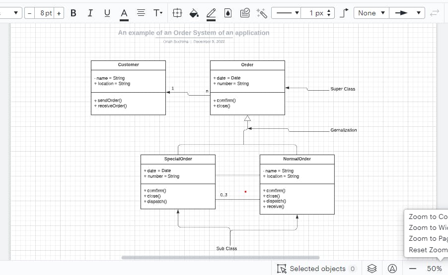
The following diagram is an example of an Order System of an application. It describes a particular aspect of the entire application.
Summary
Unified modeling language is known as UML.
It is used to build object-oriented models that depict a system's architecture and operation. Grady Booch, Ivar Jacobson, and James Rumbaugh created it.
Although it is the replacement for object-oriented languages, UML is very distinct from them. UML diagrams come in three different flavors: interaction, behavioral, and structural.
Many businesses utilize UML, which is recognized as an ISO standard, to create documentation and model designs.
What kinds of UML diagrams are there? UML diagrams typically fall into one of three categories: structural, behavioral, or interaction.
Resources
en.wikipedia.org/wiki/Unified_Modeling_Lang..
guru99.com/uml-diagrams.html#:~:text=Struct...
tutorialspoint.com/uml/uml_quick_guide.htm